Search
Close this search box.

Waveguide Cavity

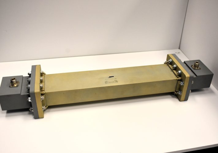
A resonant waveguide cavity which resonates at frequencies corresponding to half wavelength intervals of the cavity length
The waveguide cavity is a section of rectangular waveguide truncated with irises at both ends, therefore resonating at frequencies corresponding to half wavelength intervals of the cavity length. A small material specimen is inserted through a hole in the middle of the cavity, causing the resonance to be perturbed and that perturbation is used to determine the real and imaginary dielectric permittivity of the specimen. This method follows the ASTM D2520 standard method.

Applications of the Waveguide Cavity:

  • The waveguide cavity provides good sensitivity to the dielectric permittivity and loss tangent of low-loss dielectric materials. Accurate determination is necessary for microwave substrates, antenna materials, and radomes. Examples of how the waveguide cavity is being used:
    • Characterizing dielectric materials used for wireless communications (WiFi, Bluetooth, internet of things (IOT), etc.), radomes, medical devices, and other applications where low-loss dielectric properties are needed at radio frequencies.

Benefits of the Waveguide Cavity:

  • Supplied software automates scanning to find and accurately characterize the resonances using coarse and fine frequency sweeps.

Additional Information:

  • Other cavity designs can be developed by request.
  • Built using standard EIA waveguide sizes.
  • System can be designed to resonate at user-specified frequencies.
  • Specimen insertion holes cut to fit cross-section of materials.
  • Fed by coax to waveguide transitions with N-type, SMA, 3.5mm, or 2.92mm connectors.
  • Waveguide components placed inside an insulated enclosure for temperature stability.
  • 3D printed tools are included for specimen insertion and removal.
  • User Manual. 
  • CTGcalc™ Software.
  • Compliance with ASTM International 2520 Standard.